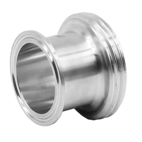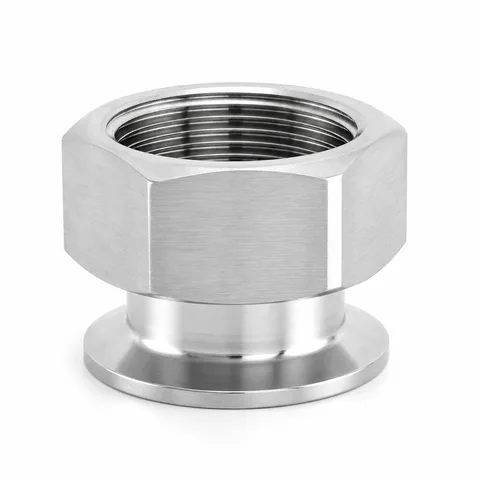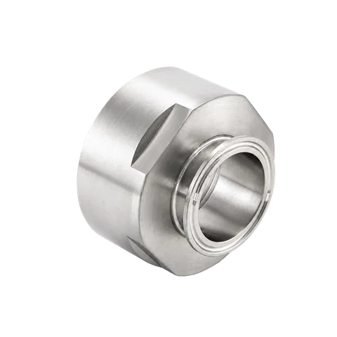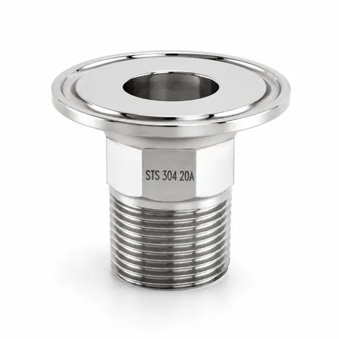








Flange #150 × Tri-Clamp Adapter
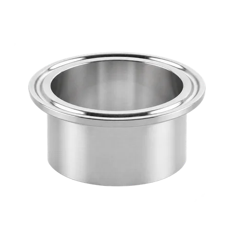
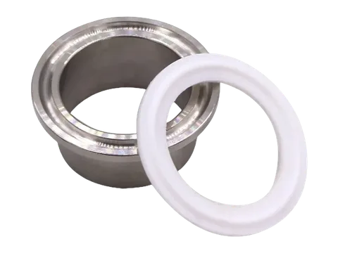
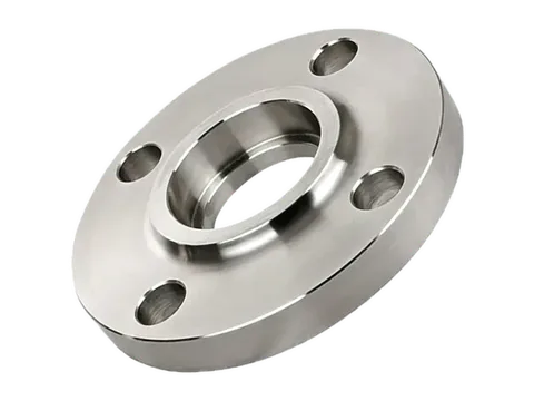
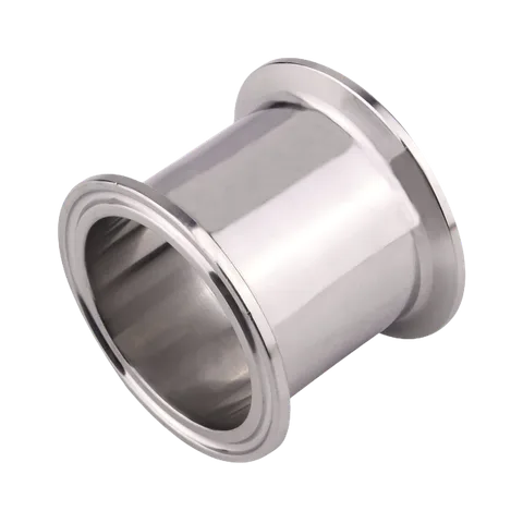
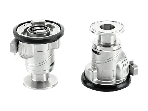
A stainless steel transition adapter combining a circular #150 bolted flange with a short Tri-Clamp ferrule neck. The reference series lists eight nominal size options from 3/4 to 6 inches, with four-hole and eight-hole flange drilling patterns shown in the 1-to-6-inch dimension chart.
Connection | Flange #150 × Tri-Clamp ferrule |
|---|---|
Reference material option | Stainless Steel 316L (body text also notes 316) |
Reference size options | 3/4" × 3/4" to 6" × 6" (eight options; chart covers 1"–6") |
End construction | Circular bolted flange with short coaxial Tri-Clamp ferrule neck |
Flange bolt pattern | 4 bolt holes (1"–3" chart sizes); 8 bolt holes (4" and 6" chart sizes) |
Size
Product overview
Transition from bolted equipment flanges to Tri-Clamp lines
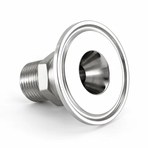
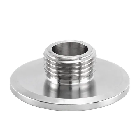
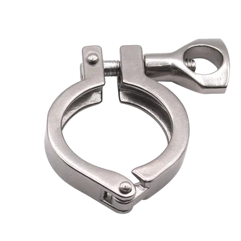
This coaxial adapter connects flanged process equipment, valves or vessel nozzles directly to removable Tri-Clamp pipework. One side forms a circular bolted flange designated #150, while the opposite side projects as a short cylindrical neck ending in a standard clamp ferrule.
Bolt circle geometry and hole count by size
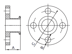
In the reference dimension drawing, the flange face is defined by overall axial length A, bolt-hole diameter B, bolt-circle diameter C and hole quantity. Sizes from 1 inch through 3 inches use a four-hole bolt pattern, whereas the 4-inch and 6-inch sizes use an eight-hole bolt pattern. Verify all four parameters against the mating flange before ordering bolts and full-face or ring gaskets.
Listed size options and chart coverage
The source product options list eight equal size combinations from 3/4" × 3/4" up to 6" × 6". Because the accompanying dimensional table covers the seven sizes from 1" to 6" and omits a row for 3/4" × 3/4", dimensions for the 3/4-inch configuration should be confirmed separately prior to installation.
Material designation and installation clearance
The product title and option selector specify Stainless Steel 316L, while the source description text refers to stainless steel 316; if low-carbon 316L material documentation is required, specify it on the purchase order. During layout, allow wrench clearance behind the flange for bolt nuts as well as radial room around the short neck to close the Tri-Clover ring.
Technical specifications
TC-ADP-FLG150 Dimension Reference
Only the listed chart specifications and units; does not extend to unlisted dimensions or other configurations.
Units: in
| SIZE | A | B | C | Qty. Of Holes |
|---|---|---|---|---|
| 1" | 1.625" | 0.625" | 3.125" | 4 |
| 1-1/2" | 1.625" | 0.625" | 3.875" | 4 |
| 2" | 1.750" | 0.750" | 4.750" | 4 |
| 2-1/2" | 1.750" | 0.750" | 5.5" | 4 |
| 3" | 1.750" | 0.750" | 6" | 4 |
| 4" | 1.750" | 0.750" | 7.5" | 8 |
| 6" | 2.188" | 0.870" | 9.5" | 8 |
Dimensional drawings
Need a different size, connection or document?
Discuss your requirements