

Two valves with the same clamp ends can behave differently in a line. The useful comparison is the flow passage, cleaning access and space needed to operate or service them. Start with the duty, then compare the specific construction rather than choosing a valve family by habit.
1. Compare the flow passage
For isolation duty, weigh the available pressure drop and installation space together.
Valve | Main duty | Practical trade-off |
|---|---|---|
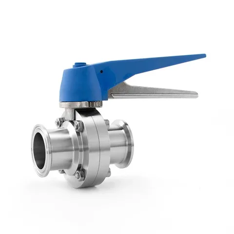
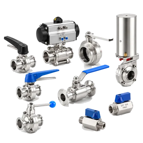
Butterfly | On/off isolation | Compact body; disc remains in the open flow path |
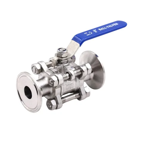
Ball | Isolation or multiport routing | Bore and cavity design determine flow and cleaning access |
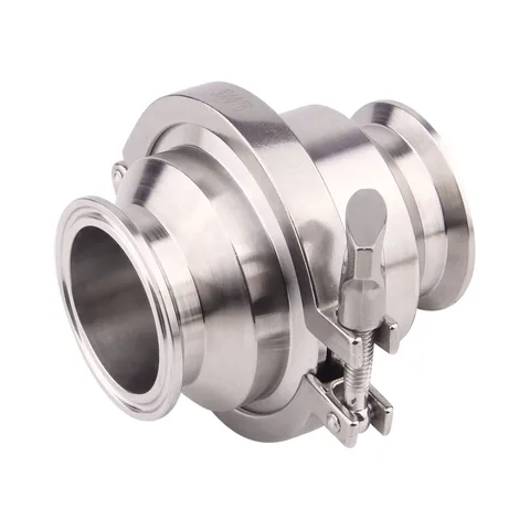
Check | Automatic reverse-flow control | Opening pressure and running pressure drop affect the circuit |
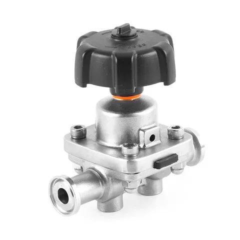
Diaphragm | Shut-off or specified regulation | Body geometry and diaphragm influence flow and drainage |
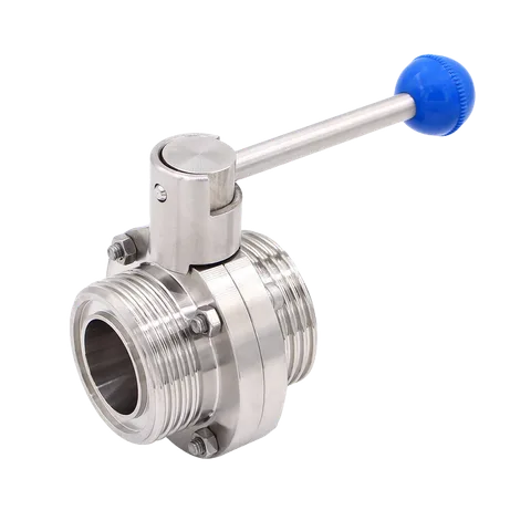
An open butterfly disc occupies part of the passage, so include its resistance in the line calculation. A full-bore ball valve can provide a more continuous passage, but not zero pressure loss. Compare Cv/Kv or pressure-drop data at the required flow; a nominal size alone is insufficient.
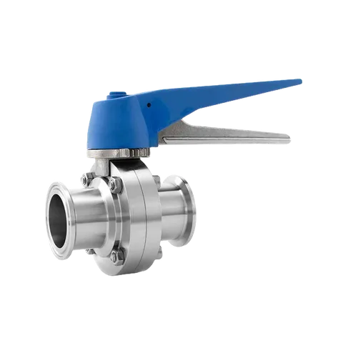 Manual clamp butterfly valveCompare disc clearance and installed lengthView product
2. Follow the cleaning path inside the valve
Review where product can remain and how cleaning fluid reaches those spaces.
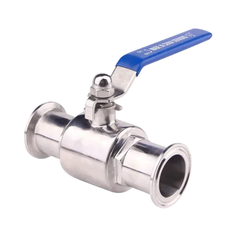
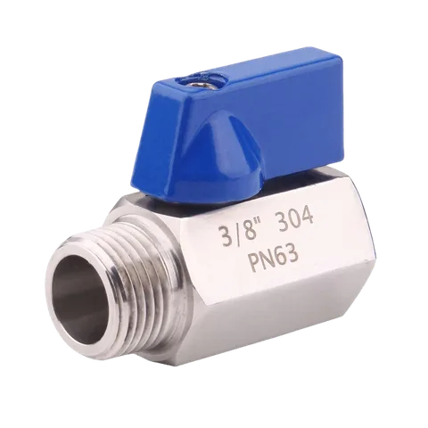
A ball valve can retain material around the ball and seats. Cavity fillers reduce that space; their presence does not demonstrate complete cleaning. A three-piece body allows body separation for maintenance, but does not identify the seat design or prove the valve is suitable for CIP.
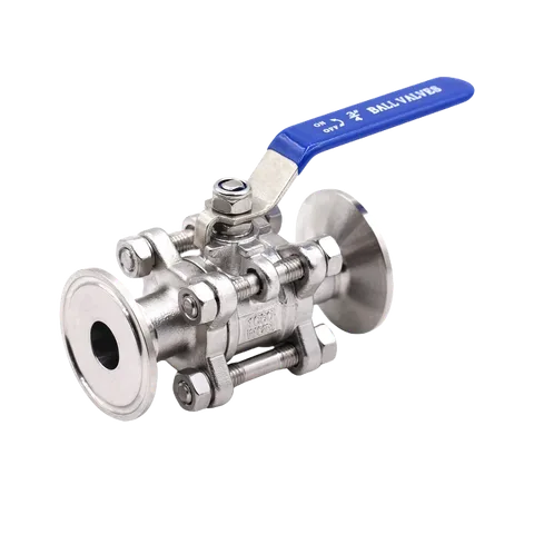 Three-piece clamp ball valveConfirm the bore and cavity constructionView product
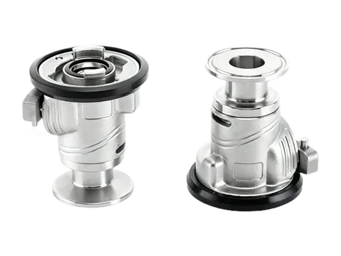
In a weir-type diaphragm valve, the body shape and installed orientation affect the drainage route. Rotation around the pipe axis is different from the pipe’s slope. Use the angle and reference position for that body and size; one universal tilt angle cannot establish drainage for every installation.
3. Treat reverse flow and actuation as separate duties
A check valve responds to differential pressure; a powered isolation valve responds to its actuator and controls.
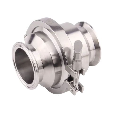
Cracking pressure is the differential at which a check valve begins opening, not its pressure drop at design flow. A low-head circuit needs both values. Spring selection and installation orientation affect operation; water-hammer assessment also needs closure behaviour and the pipe system, not just an opening-pressure number.
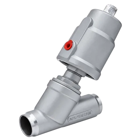
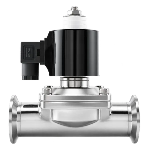
For pneumatic isolation, specify air supply, switching frequency and the required position on loss of air. Open/closed feedback reports end positions; continuous regulation requires suitable valve characteristics, an actuator and positioning control. The same mounting interface does not establish actuator sizing.
4. Match seals, ends and service access
Make the cleaning cycle and maintenance envelope part of the configuration.
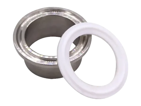
EPDM is often considered for water duties, FKM for oils and selected chemicals, and PTFE where chemical resistance matters. Review the exact compound against temperature, concentration and exposure time, including cleaning. FKM heat resistance is not a blanket steam approval; PTFE seat design must account for creep and loading.
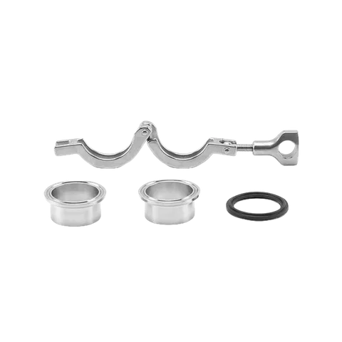
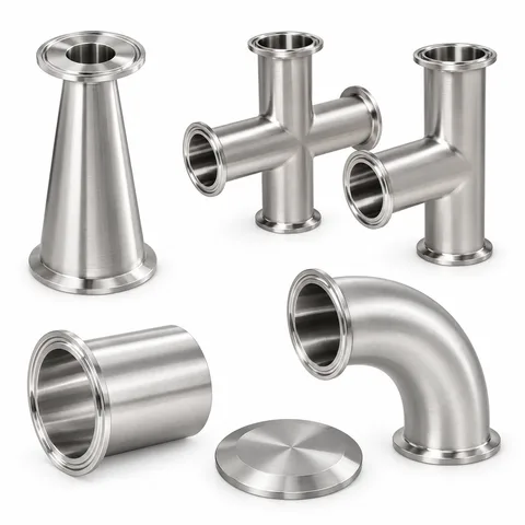
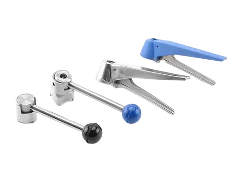
Match the ends using the fittings selection guide. Leave room for handle travel, fasteners and removal of service parts.
For gasket seating at the valve joint, use the Tri-Clamp assembly guide.
5. Compare two candidate duties
The examples below illustrate a selection process, not approved configurations of the linked products.
Water isolation: a 2–3 inch ambient-temperature process-water line, no pigging, with a defined pressure-drop allowance and limited axial space. A clamp butterfly valve is a practical candidate. EPDM can be considered after checking the actual water treatment and cleaning cycle; a hot CIP return needs a separate temperature and chemical review.
Viscous product or product recovery: syrup or a line designed for pigging calls for review of a continuous bore and product retention. Consider a full-bore ball-valve design, requesting documented cavity-filled construction where reduced retention is required. Review seat material and cleaning access together. For pigging, verify actual passage, internal steps and pig clearance through the entire route. Neither “three-piece” nor “full bore” alone establishes that capability.