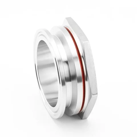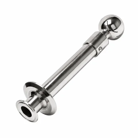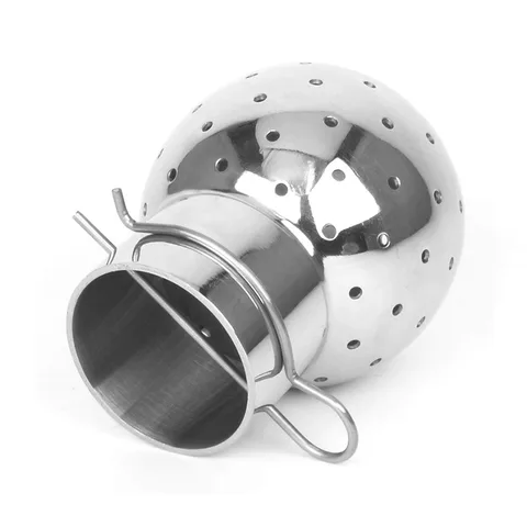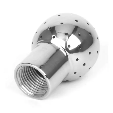
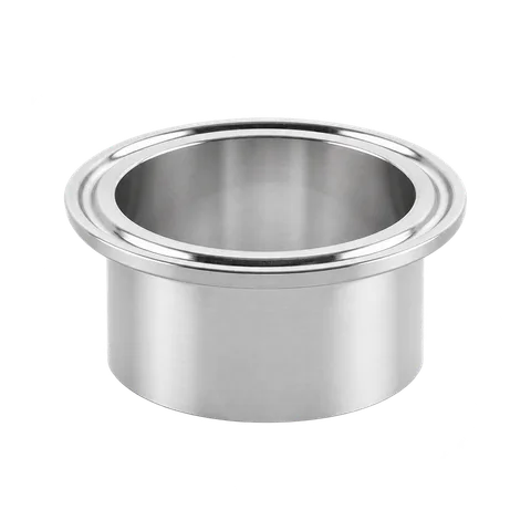
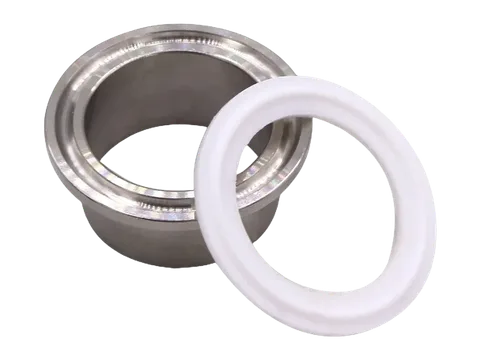
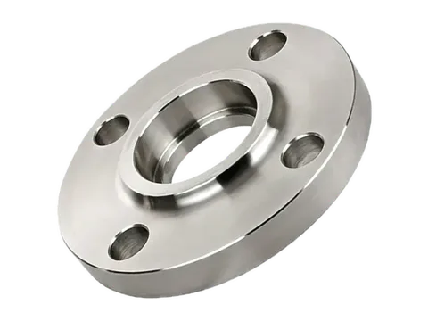
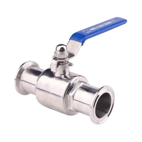
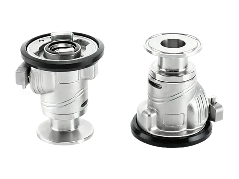








Bolted Tank-Port Flange Connector for Tri-Clamp Fittings
An SS316L tank connection assembly combining a weld-in circular base, an O-ring sealed Tri-Clamp ferrule port, a two-piece split retaining flange, and four dome nuts. Tabulated in eight sizes from 0.5" to 4" (TC 25.2 to 119).
Connection | Weld-in circular tank pad × bolted Tri-Clamp (TC) ferrule port |
|---|---|
Material | SS316L |
Assembly structure | Weld-in pad with O-ring groove, TC ferrule insert, 2-piece split retaining ring, and 4 dome nuts |
Shape | Circular pad flange assembly |
Size range | 0.5" / 0.75" / 1" / 1.5" / 2" / 2.5" / 3" / 4" (TC 25.2–119, D1 55–170) |
Size
Product overview
Weld-In Tank Pad and Split Retaining Ring
The assembly combines a multi-piece tank port assembly: a cylindrical base welds into the vessel shell or bottom head, an O-ring seats in a machined groove on the base face, and a two-piece split retaining ring clamps a flanged ferrule insert down using four studs and cap nuts.
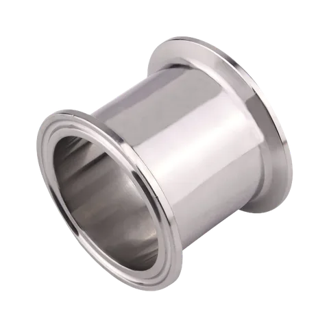
Tri-Clamp Instrument and Valve Interface
The assembly adapts a standard Tri-Clamp (TC) ferrule connection onto tank equipment so TC-ended valves or instruments can be installed or removed by unbolting the four dome nuts.
Eight Tabulated Sizes in SS316L
Manufactured in SS316L stainless steel, the dimensional chart covers eight nominal sizes from 0.5" to 4" with a 25 mm weld-pad height. Note that the 0.5" and 0.75" sizes share a 25.2 mm Tri-Clover flange and 55 mm pad OD while differing in bore diameter, and the 1" and 1.5" sizes similarly share a 50.5 mm clamp flange and 85 mm pad OD. Check the complete row for bore, tube OD, and pad diameter.
Fit-Up and Ordering Checks
Before ordering, match the bore d (9.5 to 97.6), tube OD Tube-D (12.7 to 101.6), and TC flange diameter (25.2 to 119) to your mating valve or sensor, and confirm the O-ring elastomer compound and whether the insert ferrule is supplied with the weld pad.
Technical specifications
Dimensional reference · Tank-bottom bolted connection
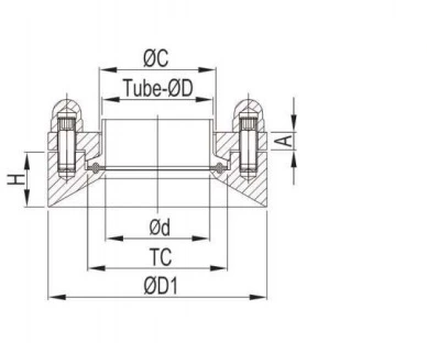
Bolted Tank-Bottom Connection Housing: listed sizes and matching drawing symbols.
| SIZE | d | Tube-D | TC | D1 | C | A | H |
|---|---|---|---|---|---|---|---|
| 0.5" | 9.5 | 12.7 | 25.2 | 55 | 20.5 | 8 | 25 |
| 0.75" | 15.8 | 19.1 | 25.2 | 55 | 20.5 | 8 | 25 |
| 1" | 22.1 | 25.4 | 50.5 | 85 | 43.5 | 8 | 25 |
| 1.5" | 34.8 | 38.1 | 50.5 | 85 | 43.5 | 8 | 25 |
| 2" | 47.5 | 50.8 | 64 | 100 | 55 | 10 | 25 |
| 2.5" | 59.5 | 63.5 | 77.5 | 112 | 65.5 | 11 | 25 |
| 3" | 72.2 | 76.2 | 91 | 131 | 78 | 12 | 25 |
| 4" | 97.6 | 101.6 | 119 | 170 | 105 | 12 | 25 |
Dimensional drawings
Need a different size, connection or document?
Discuss your requirements