


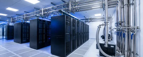
Liquid cooling manifold layout in direct-to-chip systems
A practical guide to supply and return headers, branch layout, service interfaces, mounting points and drawing-based manifold fabrication.
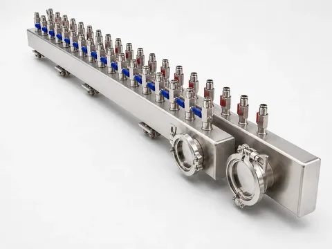
The manifold as a physical interface map
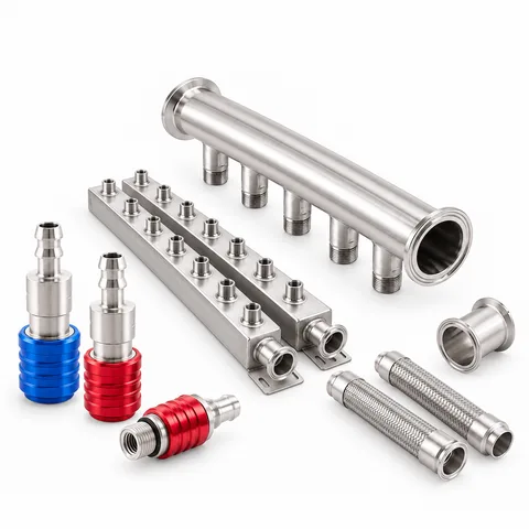
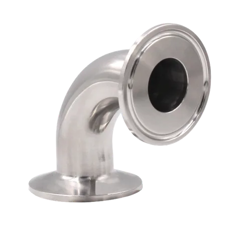
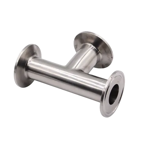
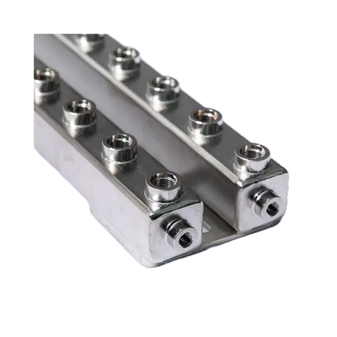
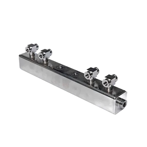
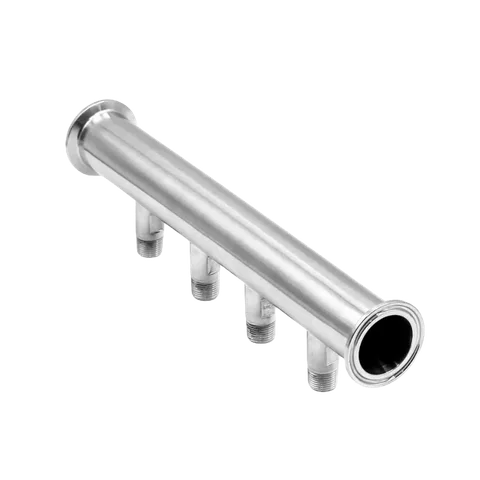
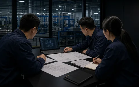
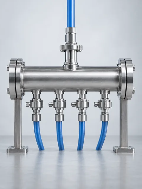
A liquid-cooling manifold organizes repeated supply and return paths between the larger loop and branch circuits. A buildable package makes branch pitch, valve orientation, connector choice, end-port access, mounting, cleaning, labeling and the test protocol visible before fabrication starts.
Details to confirm
Header size, overall length, branch count and pitch
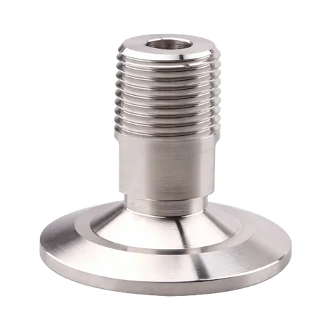
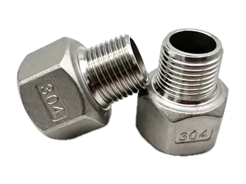
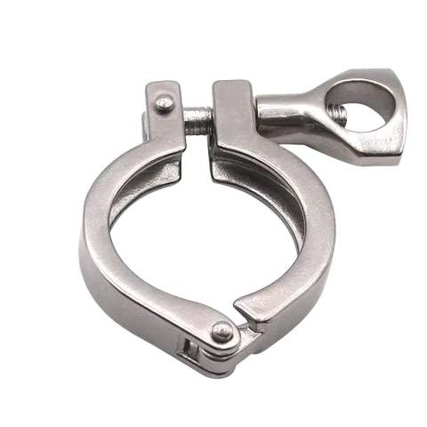
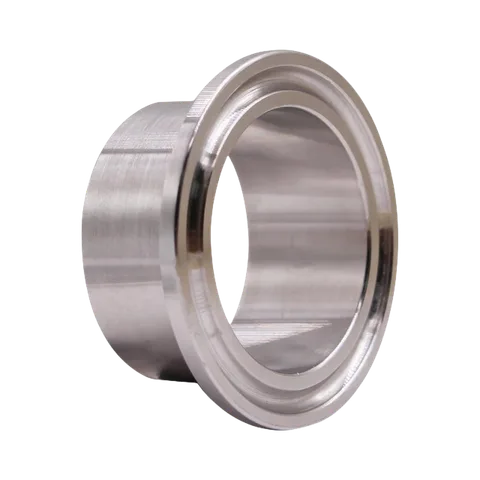
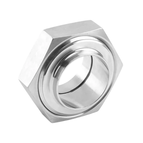
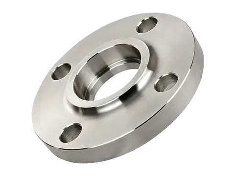
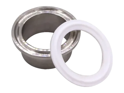
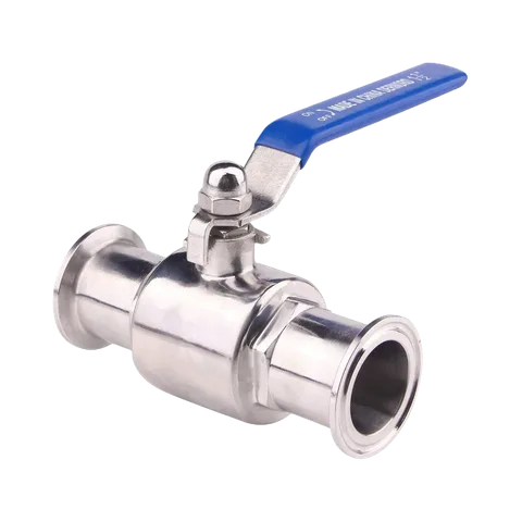
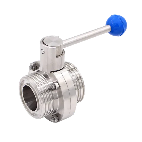
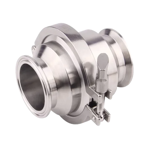
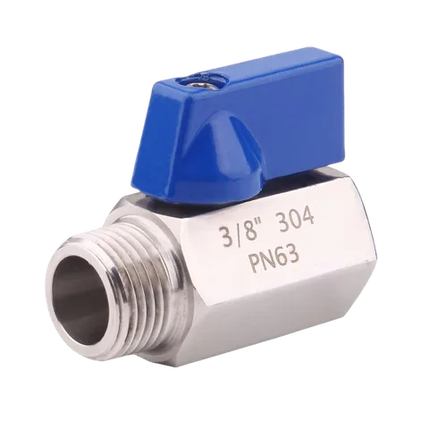
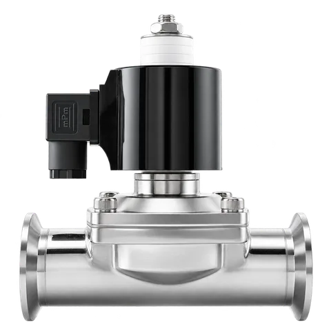
Valve, quick connector, clamp, flange, thread and sealing requirements
Mounting position, service clearance and hose bend space
Pressure, medium, temperature, hold criteria, cleaning and protected packing
Keep the boundary explicit
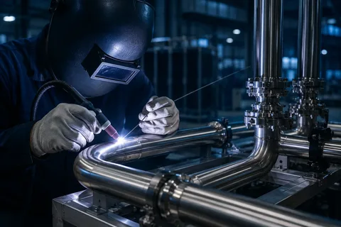
The manifold is not the complete cooling system. Customers or integrators define the architecture, CDU, cold plates, controls and acceptance criteria. Chelsey fabricates the confirmed stainless hardware from released drawings, BOMs, samples or interface requirements.
Related posts
All resources
Stainless steel sanitary fittings and pipeline solutions
A Chelsey video overview of 304 and 316L sanitary fittings and stainless pipeline hardware.
Watch video
Liquid cooling piping and stainless manifolds
A Chelsey overview of custom OEM liquid-cooling piping, manifolds and physical fluid-path hardware.
Watch video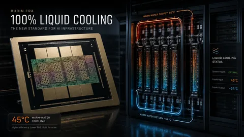
Rubin-era AI infrastructure puts fluid-path interfaces in focus
As rack-scale infrastructure moves further toward liquid cooling, manifolds, pipe modules, CDU interfaces, cleanliness and test documentation need to be confirmed earlier.
Read article